Let's talk WF1 rear lower a-arms.
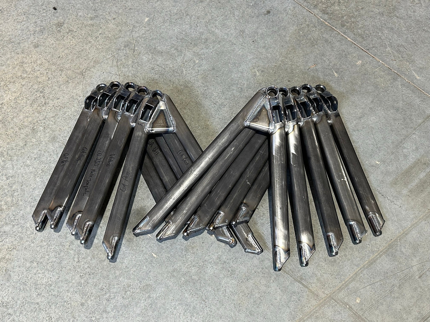
Back in May, we were just taking delivery of a fresh batch of WF1 rear lower a-arms. Since then I've fielded a few questions around some of the finer points of the design, and how it might address some of the historical issues with the WF1 rear lower a-arm. We've just taken delivery of another batch of WF1 rear lower a-arms this week, which got me to thinking, how much do people know about why WF1 a-arms are the way they are?
Well, dear reader, I have thoughts.
The venerable Stohr 01d upon which the WF1 design is based originally started life with Formula Ford equivalent mechanicals. In fact, early wheel bearings were the same size as a Swift DB1. The whole car was lightweight, intended for low-power and low-downforce usage, following the Colin Chapman dictum of "simplify, then add lightness" to its logical conclusion. This was all a reasonable starting point for a car some 200-300lbs lighter than a DB1 with only 165hp on tap.
Then we started piling on downforce. Like, a lot of downforce. Thousands of pounds of the stuff. Rules evolution has resulted in 200-300lbs increased minimum weight, and we've all been the beneficiary of engine manufacturer horsepower wars for the last 20 years. Predictably, things started breaking on the WF1, and the rear lower a-arms were especially vulnerable to all this added load and abuse.
Now, while these factors undoubtedly contribute to the challenge, amazingly none of those things are actually the real problem.
The angle of the dangle
The WF1 was designed with ultra-low rear suspension to lower the bodywork and clear out cross-sectional aerodynamic area in the hunt for maximum speed. The rear upper suspension is only a few inches higher than the axle half shaft, and the rear bodywork practically sits on the suspension. A knock-on effect of all this is the rear pushrod has to be laid over at a fairly extreme angle to get it to fit under the bodywork.
And therein lies the issue. The rear suspension needs to transmit all those loads from the outer lower spherical at the upright to the pushrod attachment at the bellcrank inboard. But when you combine the pushrod angle with the need to provide mechanical clearance between the a-arm leg and the pushrod rod end, and you end up with a load path with a nice little 4+ degree dogleg instead of the ideal laser straight line:

Doesn't look like much, does it? To put it in perspective, some finite element analysis is in order. I fixtured the a-arm with bearings at the inboard ends, along with the inboard end of the pushrod. There's a pivot between the pushrod and a-arm bracket. Then I applied a simultaneous load of 1000lbs vertical with 1500lbs lateral fed into the spherical bearing cup to simulate 3+ G's of cornering with a generous safety factor.
Here's what happens to displacement and yield stress when you put a load on it. Red is bad, y'all:


Look familiar? As you can see, there is quite a lot of bending and twisting going on in the rear leg of the a-arm. Flex it enough that way, and you get a stress crack across the top of the tube on the rear leg of the a-arm. Typically right at or just inboard of where the pushrod bracket attaches to the tube, right where those circled red hot spots are. Bad ThingsTM happen at this point.
So, what to do about it?
All manner of solutions have been tried over the years, with varying success:
-
Thick wall round tube rear leg
-
Double-tube rear leg - stuff a round tube just inside the aero tube with rosette welds along the length of the rear leg
-
Significantly extend the inboard anchor point of the pushrod rod end bracket, nearly to the middle of the rear leg
-
Thick vertical shear web inside the rear leg
Sadly, most of these solutions really only modestly extend the time to failure of the a-arm. The thick vertical shear web approach has been the most effective of these, resulting in an a-arm that can largely stand up to the abuse of high-downforce induced loads, surviving thousands of miles of track use by reducing yield stresses in the rear leg of the a-arm. Here's how the thick vertical shear web impacts the a-arm:


The bending displacement is still there, but the yield stress is definitely reduced. It's a reasonable solution to the engineering challenge, but it requires quite a bit of added weight to reach the level of bracing necessary.
Which brings us to today
Our a-arms do not use a vertical shear web, because we stubbornly refuse to accept added weight as an inevitable byproduct of making the rear lower a-arm survive. Instead, we took an approach that seeks to reduce or eliminate the inherent stress down to manageable levels, rather than adding enough bracing to withstand the beating. Our approach was simple, align the pushrod with the natural axis from the outer spherical and the pushrod attachment at the bellcrank:

The complication is this puts the pushrod rod end below the surface of the tube, so rather than putting brackets on top of the tube, we've created a boxed-in full-depth pocket that takes up all the loads from the pushrod and feeds them into the bearing cup. Minus the a-arm legs, it looks something like this:

And here is the resulting displacement and yield stress with this geometry. Same loads as before, but with a very different outcome:


By realigning the pushrod to the natural force line from the spherical bearing to the bellcrank, the bending and twisting moment is radically reduced. In turn, yield stresses in the assembly go down significantly, and we can accomplish the goal without adding weight. This is a virtuous cycle that improves the lifespan of all of the parts concerned.
Is that the end of the evolution?
Nope. We consider our current rear lower a-arm design to be the right engineering path, but their fabrication complexity (and aesthetic execution quality) leaves something to be desired. So rather than the existing multi-piece outer weldment (bearing cup, channel bracket, and three caps) the next version will have a single-piece billet outer receiver that distributes even more of the stress and is radically simpler to fabricate, tipping the same lightweight scales as our current a-arms:


No more yield stress hot spots, nice linear displacement without twisting, decreased time to fabricate, and improved design quality.
What's not to love?